Horizontal deflections in the planes of bents and shear walls can be computed on the assumption that they act as cantilevers. Deflections of braced bents can be calculated
by the dummy-unit-load method or a matrix method. Deflections of rigid frames can be computed by adding the drifts of the stories, as determined by moment distribution
or a matrix method.
by the dummy-unit-load method or a matrix method. Deflections of rigid frames can be computed by adding the drifts of the stories, as determined by moment distribution
or a matrix method.
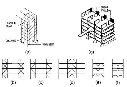
Figure showing Building frame resists lateral forces with (a) wind bents or (g) shear walls or a combination of the two. Bents may be braced in any of several ways, including (b) X bracing, (c) K bracing, (d) inverted V bracing, (e) knee bracing, and (f) rigid connections.
For a shear wall (Fig) the deflection in its plane induced by a load in its plane is the sum of the flexural deflection as a cantilever and the deflection due to shear. Thus, for a wall with solid rectangular cross section, the deflection at the top due to uniform load is
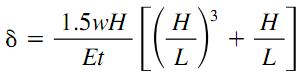
where
w = uniform lateral load
H = height of the wall
E = modulus of elasticity of the wall material
t = wall thickness
L = length of wall
w = uniform lateral load
H = height of the wall
E = modulus of elasticity of the wall material
t = wall thickness
L = length of wall
For a shear wall with a concentrated load P at the top, the deflection at the top is
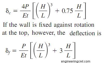
Units used in these equations are those commonly applied in United States Customary System (USCS) and the System International (SI) measurements, that is, kip (kN), lb /in 2 (MPa), ft (m), and in (mm).
Where shear walls contain openings, such as those for doors, corridors, or windows, computations for deflection and rigidity are more complicated. Approximate methods, however, may be used.
0 comments:
Post a Comment